
Tutorial
Tutotial in Spanish/Traducción al español del tutorial realizada por Daniela Ávido
After installation, please walk through this tutorial to get accustomed to the way Regard3D works. After that, you should know how to create your own projects!
Adjust settings
First, make yourself comfortable with the 3D-control of Regard3D. After Regard3D is started, you will see the name "Regard 3D" in actual 3D. Try to rotate it by using the left mouse button, zoom in and out using the mouse wheel or the middle mouse button, and pan using the right mouse button.
If you would like to change the mouse button or wheel assignments, go to the Menu Options -> Properties... to change them. Here you can also change the default project folder.
Find test data
I suggest to use a small test data set from the internet. Here are some good sources:
- A small dataset is called "kermit" and is part of bundler by Noah Snavely. Go to this site: Bundler homepage, then download the most recent source package. Extract it, and you will find the pictures under examples/kermit. These images are very small (640x480) and are processed within seconds.
- Another relatively small dataset is the "Sceaux Castle" by Pierre Moulon. You can download it by clicking on this link: Sceaux Castle. Extract the ZIP file somewhere on your hard disk.
- A high-quality dataset has been created by Romuald Perrot: Reconstruction Data Set. These images have a very high resolution and take long to process, but they lead to high-quality results.
There are many more data sets on the internet. Please always respect the license conditions of the contributors.
Create new project
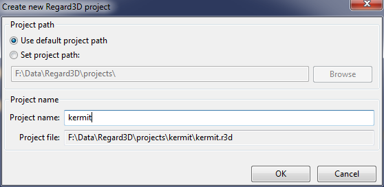
Now, let's create our first project. Click on the "Create new project"-button (the one with an empty sheet and a big green plus sign) or use the menu File -> New Project... . Check whether the directory is correct, and enter a project name.
After clicking OK, you will see a new item on the left labeled "Project: kermit" (or whatever your project name was). This is the project tree, which we will fill in the next few steps of this tutorial.
Make sure the project item is selected, and click on the button "Add Picture Set.." below (or use the context menu with the same name). A new dialog pops up, where you can define the picture set. As the name suggests, a picture set consists of a number of pictures of the same object. Add the pictures you downloaded earlier. Eventually it will look similar to this:
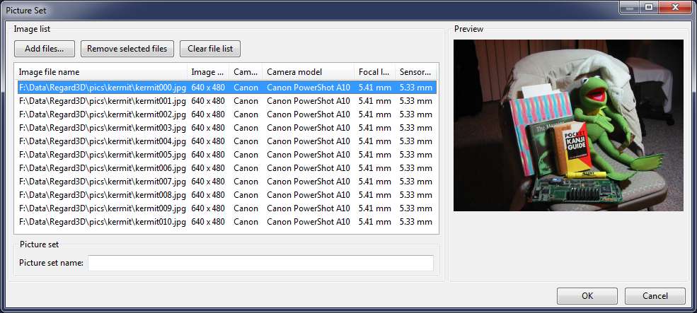
Click OK. The project tree consists now of an additional element, the Picture Set 0.
Compute matches
The next step is called "compute matches". It will detect keypoints in each image and match them with keypoints from other images. To start, select the picture set item in the project tree and click on "Compute matches...". A new dialog appears:
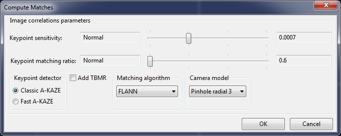
For a small dataset like kermit, move both sliders fully to the right. For larger images, start with a small value and only increase the settings if necessary.
After clicking OK, your computer will compute the matches. Depending on the amount of pictures, the size of the pictures and the selected parameters this will take from a few seconds to minutes.
Tips:
- For big datasets, start with the lowest settings (sliders to the left). If you do not receive satisfying results, increase the keypoint sensitivity first. If you still need more matches, increase the matching ratio.
- Add TBMR if you need more keypoints in some areas (TBMR tends to distribute the keyponts better than A-KAZE)
- Use the other settings on their defaults
Triangulate
When the matches are computed, you can start the triangulation step. Make sure the "Matches 0" item in the project tree is selected and click on the "Triangulation..." button. A new dialog appears:
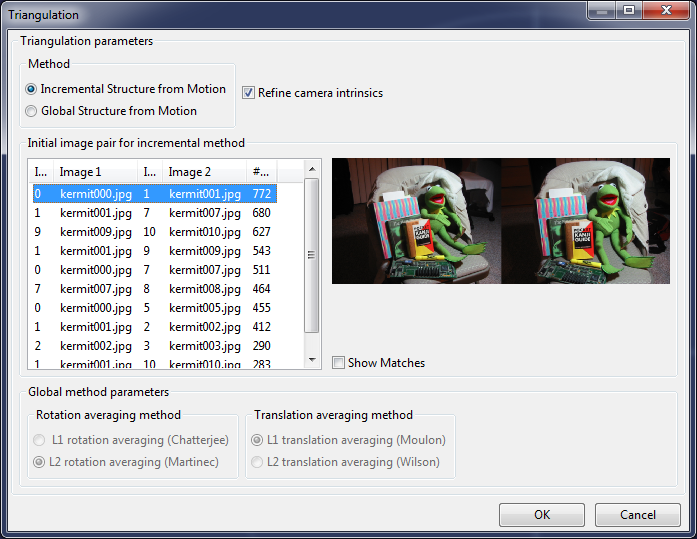
You have the possibility to select one of two triangulation engines:
- Incremental: It starts off with the selected image pair and tries adding other images. Each step will perform a bundle adjustment to determine the camera parameters and the 3D positions of the keypoints ("tracks").
- Global: This engine tries to find the camera parameters and 3D positions of the keypoints globally by using all images in one step. In the current version, this engine is only available if all pictures are taken from the same camera and with the same zoom setting ("focal length").
After clicking "OK" the selected engine will run. When it is finished, a dialog will show the results. The most important figures are "Cameras calibrated/total". For example, if it says "11/11", all cameras have been calibrated, i.e. the 3D positions and parameters of all pictures has been found. If not all cameras have been calibrated, you can try again using a different method or different starting pair.
The triangulated keypoints ("tracks") and the cameras are now displayed in the 3D view. To improve visibility, increase the point size with the slider on the top right.
Densification
The triangulated point cloud is rather sparse, it is difficult to make out the original object. To densify the point cloud, make sure the Triangulation item in the project view is selected and click on "Create dense pointcloud...". The following dialog appears:

You have the option of two different sets of tools:
- CMVS/PMVS by Yasutaka Furukawa (see this homepage: Clustering Views for Multi-view Stereo (CMVS))
- MVE (Multi-View Environment) by Michael Goesele, Simon Fuhrmann and others (see this homepage: Multi-View Environment)
- SMVS (Shading-Aware Multi-View Stereo) by F. Langguth and others (https://github.com/flanggut/smvs)
I suggest to try out all of them to find out their advantages and disadvantages.
Tips:
- For small projects, deselect "Use visibility information (CMVS)". CMVS tends to generously throw away pictures.
- For large projects (many pictures) CMVS is necessary, otherwise PMVS's memory consumption and running time will "explode".
- For a first try, set parameters such that the result is computed quickly: Level 2 or 3/Scale 2 or 3, and then decrease these parameters to produce improved results
- If too much outliers are produced, increase the threshold
Surface generation
Since we still have a "point cloud" (a set of 3D points with color), we would like to generate a surface that connects (most of) these points. Select the Densification in the project tree and click on "Create Surface...".

Here we have again the option of two different set of tools:
- Poisson Surface Reconstruction, by Misha Kazhdan and others (see this homepage: Screened Poisson Surface Reconstruction)
- Floating Scale Surface Reconstruction (FSSR) by Simon Fuhrmann and Michael Goesele (see this homepage: Floating Scale Surface Reconstruction)
If the densification was done using CMVS/PMVS, only Poisson Surface Reconstruction can be used. If MVE was used for densification, I suggest to use FSSR.
For both methods, the most important parameter is the depth (Poisson)/levels (FSSR) which defines how fine the resulting mesh will be.
For colorization, two methods can be used:
- Colorizing vertices: Each vertex (edge) will have a color
- Textures: Create textures to have much finer color detail
I suggest to first use colored vertices to see the result of the surface reconstruction. If this is satisfying, create another surface using textures.
Creating textures requires much more time and memory.
Summary
Congratulations! You have made it through the tutorial of Regard3D. Now you know the basics of how to create a 3D model with Regard3D.
The project will be stored on your computer including all intermediate results. You can delete intermediate steps, add new runs with different parameters etc. To see an intermediate result in 3D, simply double-click it in the project tree.
If you want to export models (only possible for densifications and surfaces), select them in the project tree and click on "Export point cloud"/"Export surface". They will be exported in either PLY format (Stanford Polygon, densifications and surfaces without textures) or OBJ format (Alias Wavefront object).